Marcus G. Langseth Specs and Features
The Langseth is the only UNOLS vessel equipped to carry out marine multichannel seismological research. The Langseth is able to deploy multiple hydrophone arrays and linear sound source air gun arrays, which improve the quality and reliability of data acquisition, as well as enhanced general-purpose capacity, such as wireline coring, OBS deployment/recovery, and ROV operations in support of a wide range of marine science programs in locations around the world.
The R/V Marcus G. Langseth is a 235-foot, 3834-gross ton research vessel owned and operated by Lamont-Doherty Earth Observatory of Columbia University. The R/V Langseth replaced the R/V Maurice Ewing, which ended a distinguished career in early 2005.
The Langseth is classed by the American Bureau of Shipping as A-1 Baltic Ice Class IA and Coast Guard inspected; certificated to carry a total of 55 personnel of which approximately 20 are the ship's crew.
Originally constructed as a seismic vessel, the Langseth was acquired in 2004, modified, and outfitted to perform the tasks required of a general purpose research vessel. This includes hull mounted 3.5 kHz Sub-Bottom Profiler, 12 kHz transducers, and a Simrad 1x1 degree deep ocean multibeam swath bottom mapping system. In 2006, the Langseth added the Kongsberg EM122 Multibeam array transducers for 3D multibeam surveying.
Particularly unique to the academic research vessel are the extensive geophysical capabilities, which include a Sercel SealXI (408) seismic recording system with four 6.75 km of Sentinel Solid Acquisition Section (SSAS) 3 kHz solid-state hydrophone streamer cable and a 2000 psi, 40 pneumatic sound source array towed in four "strings" that can be configured either as a single, 2D source, or dual, alternating 3D source arrays.
The Langseth started conducting science operations offshore as of February 2008.
Specifications
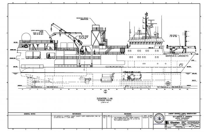
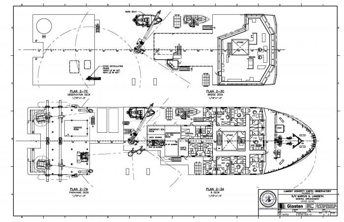
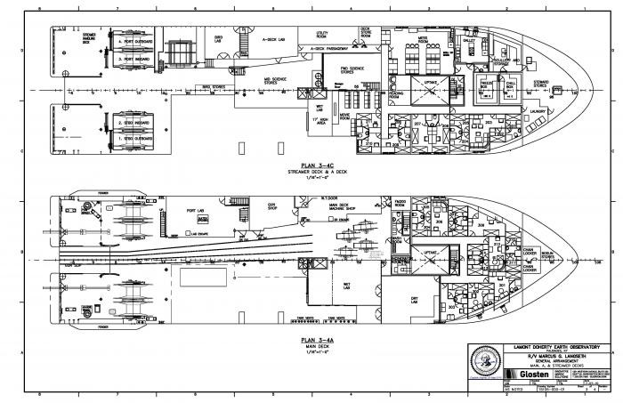
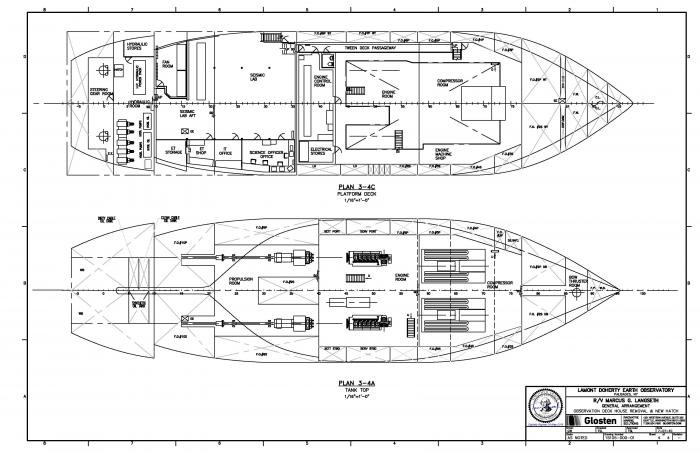
Download: Vessel Schematics (PDF) / AutoCAD Files (DWG)
General Arrangement Outboard Profile
Upper Decks
Main, A, and Streamer Decks
Observation Deck House Removal and New Hatch
There are 12 laboratory spaces aboard the R/V Marcus G. Langseth located on three decks. The spaces are all supported by an air-conditioning system that provides both heating and cooling as required. Additional deck space is available for lab or refrigerator vans.
Main Lab
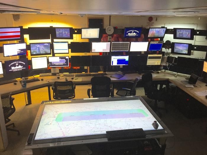
Starboard Side Forward Dry Lab
Includes tables, sinks, refrigerator, freezer, acid cabinet, and Millipore H2O system.
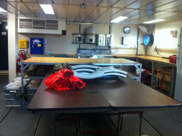
Starboard Side Aft Wet Lab
Includes tables, sinks, PCO2 sampling machine, and uncontaminated seawater.
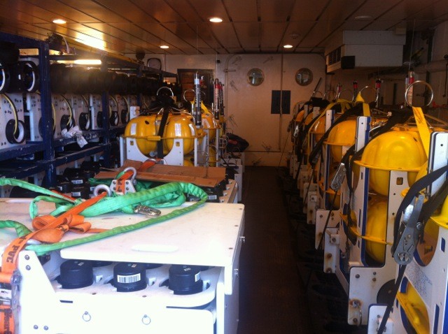
OBS gear are seen here filling the space.
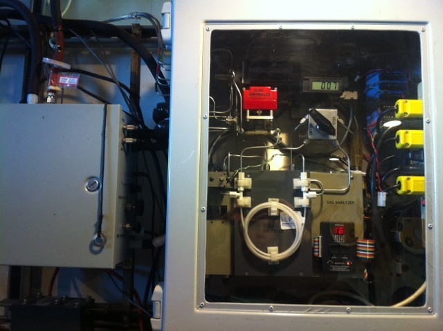
Port Lab
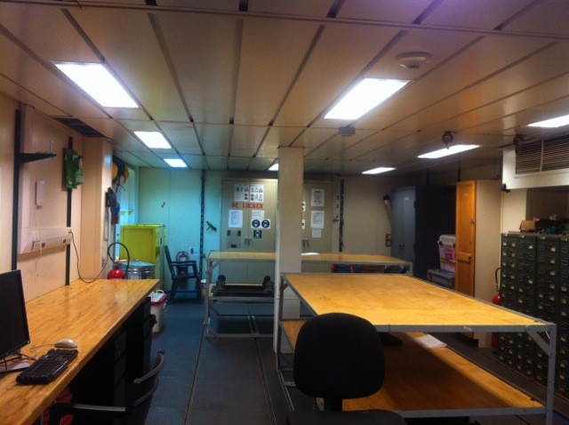
Bird Lab
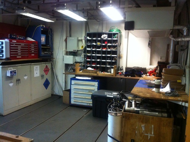
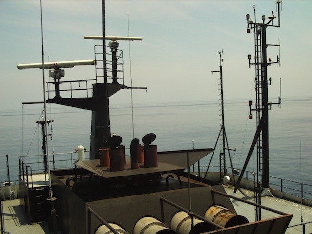
The R/V Marcus G. Langseth is equipped with a number of positioning systems used for navigational capabilities as well as survey calculations and data processing. Knowing where the ship is and the data collected is extremely important for many reasons.
Vessel Positioning Reference Systems
All survey calculations will use the World Geodetic System 1984 datum (WGS84) UTM Zone (TBD at sea) projection. The Global Positioning System (GPS) operates on the WGS84 datum. The vessel’s Differential GPS (dGPS) Reference Stations are defined in the WGS84 datum.
In order to obtain optimized navigation, waypoints need to be in decimal degrees (DD) to five (5) decimal points. Decimal degrees express latitude and longitude geographic coordinates as decimal fractions and are used in many Geographic Information Systems (GIS), web mapping applications such as Google Maps, and GPS devices. Negative numbers represent latitudes south of the equator and longitudes west of the Prime Meridian. Example: 38.88972, -77.00888
The geodetic and projection parameters are detailed in the following tables:
Project Geodetic Parameters
Global Positioning System Geodetic Parameters
Survey (Local) Geodetic Parameters
Datum Transform Parameters: Global to Survey Datum
Project Projection Parameters - Example (different based on the location of the cruise)
Gravity Tie Point
Per standard procedure, a gravity tie will be done before and after the cruise.
Positioning Reference Systems
Two independent standard multi-station dGPS systems are required for the survey.
Magnetic Declination
Magnetic declination is the angle between compass north (the direction the north end of a compass needle points) and true north (the axis around which the earth rotates). Magnetic north is determined by the Earth's magnetic field and is not the same as true (or geographic) north. Depending on where you are on the Earth, the angle of declination will be different - from some locations, the geographic and magnetic poles are aligned so declination is minimal, but from other spots, the angle between the two poles is pretty big.
Declination is calculated using the current International Geomagnetic Reference Field (IGRF) model. While results are typically accurate to 30 minutes of arc, users should be aware of several factors that can cause disturbances in the magnetic field.
- The accuracy of the model will worsen at locations close to the magnetic poles.
- As the time from the epoch of the model increases, uncertainties in the estimate of secular variation will result in an increasingly large difference.
- Magnetic minerals in local geological formations cause magnetic anomalies that can sometimes be very large. These cannot be reproduced by reference field models.
- Large magnetic storms can temporarily cause large changes in the magnetic field, especially at high latitudes.
The IGRF is a series of mathematical models of the Earth's main field and its annual rate of change (secular variation). For every cruise, magnetic declination is computed based on the date and position using a magnetic field calculator.
Science Equipment
The R/V Marcus G. Langseth has an excellent multi-channel seismic (MCS) acquisition system.
Seismic Equipment
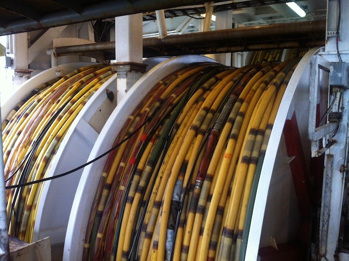
The Langseth can tow up to four seismic hydrophone cables. The cable itself is Solid Streamer [not oil-filled] manufactured by Thales [now supported by Sercel] in 150-meter sections. Each section has 12 hydrophone groups, which are, therefore, 12.5 meters long. Enough cable is being purchased to allow up to four 6-km streamers to be deployed at the same time. If a smaller number of cables are to be deployed, greater lengths are possible. The manufacturer recommends a 10-km maximum length, due to strength limitations, and this refers to new cables. Lamont policy is to restrict maximum length to 8 km.
Separation between cables towed by the Langseth can vary between 50 and 200 meters. With dual sound sources [deployed between 25 and 100 meters apart, respectively] this results in CDP line spacing between 12.5 and 50 meters. CDP line spacing should be chosen according to the desired frequency content and maximum cross-dips to be imaged.
The Langseth seismic source array comprises four identical 10-airgun strings. Four 2D or other single-source work, between one and four strings can be deployed, depending on the needs of the survey. During twin-source multi-streamer 3D surveys, the sources are split, each "side" with one or two strings.
Source and receiver navigation are determined and logged using the 3D version of the Concept Systems "Spectra" software. Positioning inputs include:
- Ship's position and heading
- Streamer compasses
- Streamer Tail buoy GPS
- Acoustic network - ship, source arrays, streamers
Concept's "Sprint" software and personnel are available for post processing of the real time acquisition positioning data, and a new package, "Reflex," which does 3D CDP binning analysis, has been purchased.
Data are recorded to disk in real time.
Seismic Source Arrays
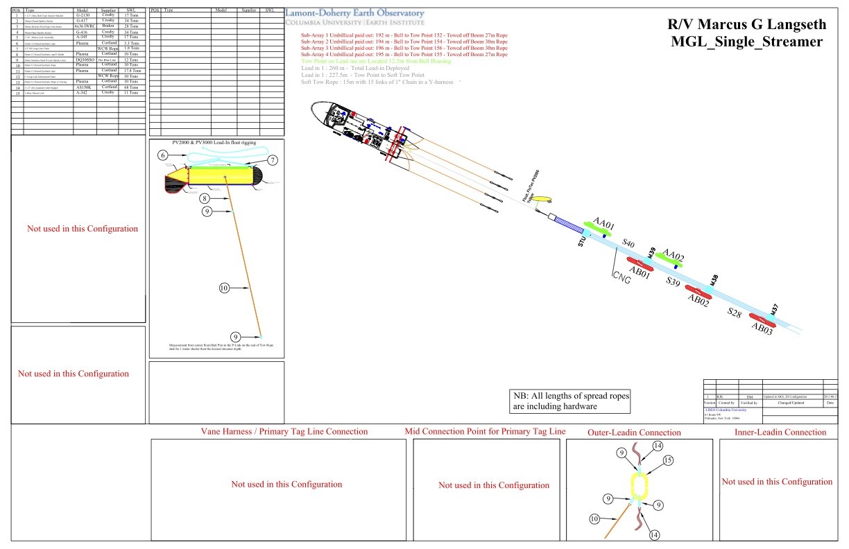
Langseth is equipped to tow four linear subarrays of airguns, each up to 16 meters long. Each string looks like this:

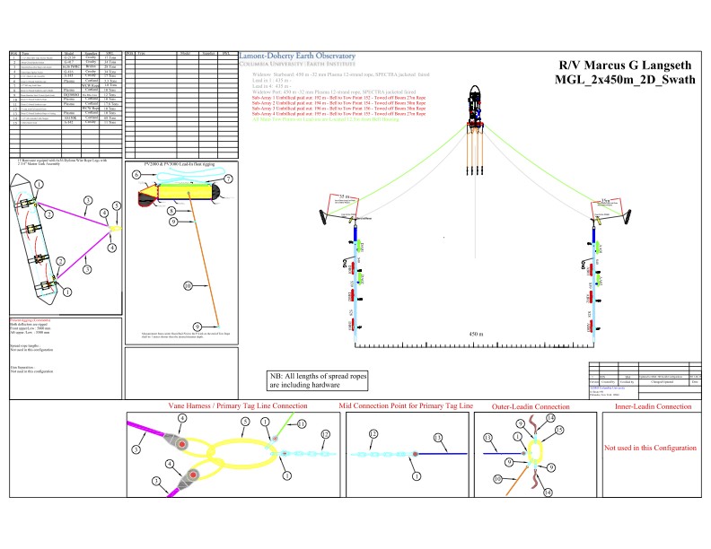
For 2D surveys, between one and four strings can be towed as a single array, depending on penetration requirements.
The single streamer array design is shown here in schematic plan view:
The 2-string 2D array design is shown here in schematic plan view:
For 3D surveys, two arrays are formed, each with either one or two strings. The 4-string 3D array design is shown here in schematic plan view:
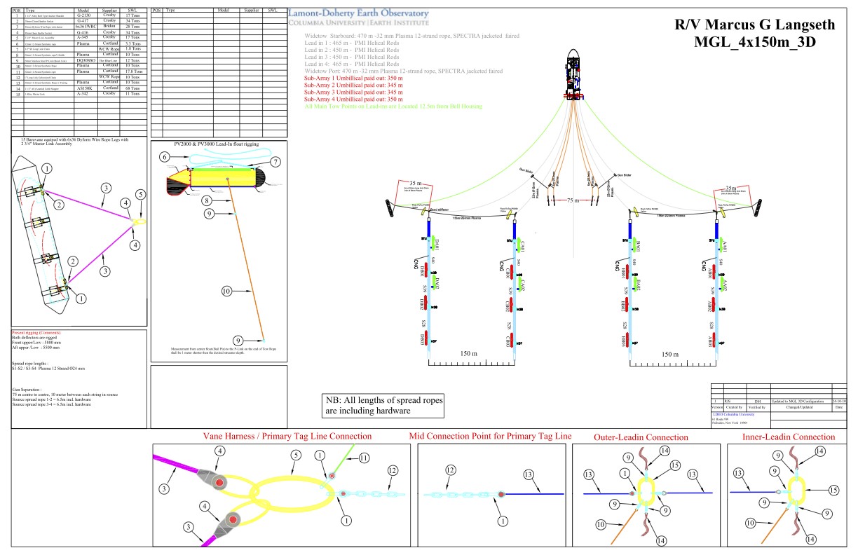
The four identical source strings can be subdivided for dual source 3D acquisition. Either one or two strings can be used for each "side," depending on source level requirements. In addition, one or two strings can be used as alternative, lower-power 2D sources, if desired.
Shooting Plan
A shooting plan will be developed and approved by the PIs and the Chief Science Officer during the cruise mobilization. The shooting plan should not be deviated from without written authorization from both. The plan must take into consideration known issues such as shallows, obstructions, fishing or other activity, protected marine areas, prevailing strong currents, and weather. In some cases the Captain and/or Marine Operation Manager may also have to provide approval if safe operation or safe navigation of the vessel is in question. A copy of each approved version of the shooting plan is kept with the documentation for the science cruise. Any changes to the shooting plan must be discussed with the Chief Science Officer first, then agreed upon changes are brought to the Captain.
Be aware the following:
- Use shot point 1001 for the start of each pre-plot, run-out shot-point is NOT included in pre-plots.
- A 4250 m run-out (85 shot-point) should be added to all lines.
- Run-in should be min. 8 km to ensure that the streamer is straight before start of line (SOL).
- For this mission, some of the lines will be starting from near-shore and run out. In these cases, run-ins will be done “as best possible” given the operational circumstances and as agreed upon between the PIs, CSO and Captain.
Deployment of four streamers naturally takes longer than it does for one. When working in a new area where reballasting is required, at least two days should be allowed for deployment. When this is not required, the process may be completed in a 24-hour period.
Seismic Parameters (example setup)
Seismic Recording Systems
Seismic Streamer
Seismic Source
In Sea Positioning Systems
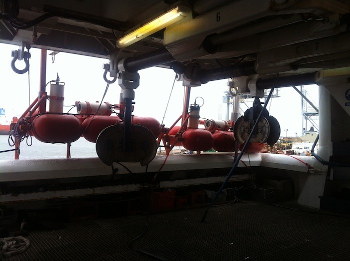
Tailbuoy
A Tailbuoy will be deployed at the tail of each streamer for positioning. Each Tailbuoy is to be fitted with a GPS unit, a radar reflector, a strobe light, and a DigiCourse Acoustic transponder for ranging to the transponders on the tail of each streamer.
Source Positioning
Each Sub-Array float will have a Posnet rGPS Pod installed along with each sub-array having a DigiCourse acoustic pod.
Streamer Positioning
Streamers are positioned using a combination of DigiCourse 5010/11 compass birds and DigiCourse acoustic transponders.
Magnetic Compasses and birds
The compasses and birds will be mounted at 300 m intervals on the streamer. The depth controllers / compasses will be DigiCourse model 5010 / 5011.Extra compass birds will be mounted in the front and tail of the streamer for redundancy.
Acoustic Positioning
Digicourse Digirange Acoustic Pods will be mounted on the streamer cable. The units mounted at the head of the Streamer will range to the Acoustic Transponder Pods co-located with the rGPS units on the Sub-Array Floats. Other units will be located in the middle of the streamer and will cross range to the units on the other streamers (if applicable). Units are mounted at the tail of the streamer which will range to the tailbuoy transponder co-located with the rGPS unit and/ or the other streamers (if applicable).
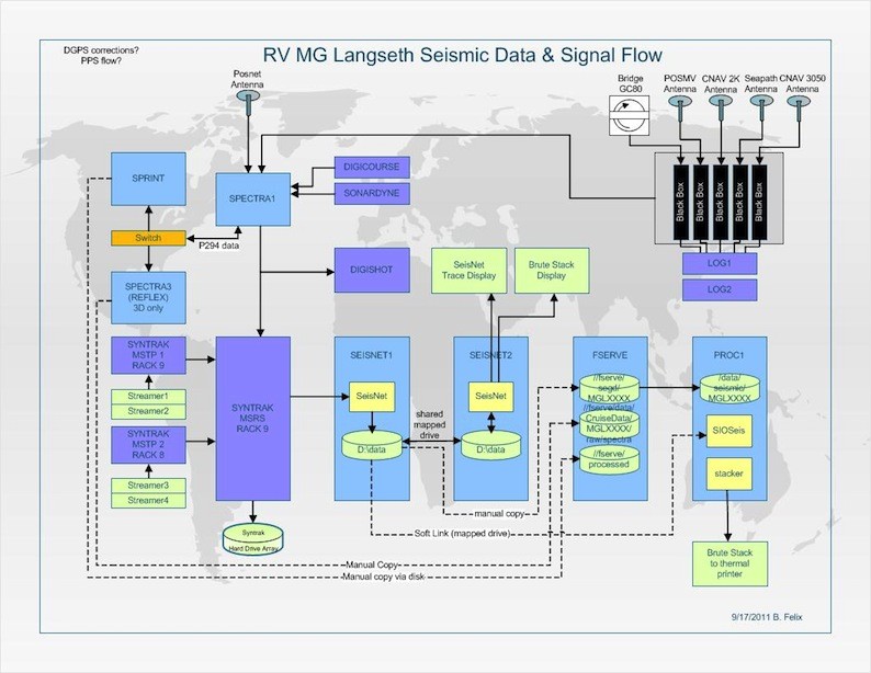
The seismic data flow is illustrated here:
Acoustic Measurements
The strength of the air gun pulses can be measured in a variety of ways, but National Marine Fisheries Service (NMFS) commonly uses “root mean square” (in dB re 1µPa [rms]), which is the level of the received air gun pulses averaged over the duration of the pulse. The rms value for a given air gun pulse is typically 10 dB lower than the peak level, and 16 dB lower than the peak-to-peak level (McCauley et al., 1998, 2000a,b).
Seismic Processing
Seismic processing is done by the science party. Seismic workstations can be provided on the vessel. Software is available on the vessel: Syntrak, SeisNet, Focus, and ProMaxx.
Line Name Convention
Surveyed lines will be labeled in a logical and unique manner. Lines names will include the cruise number, then the line number, and lastly the line type. Line numbers will start at one and increment sequentially during the survey. Lines will be identified at the end of the line name as Prime (P), Reshot (R), or Infill (I). The line names can have a maximum of 12 characters.
Example: MGL12201001P
Cruise Number: MGL1208
Line Number: ------------1001
Line Type: ------------------P/R/I
P = Prime, R= Reshot, I= Infill
“Infill” lines used only in 3D mode.
CMP Line Numbers will start with 1001 for the first line and increase chronologically. The Pre-Plot (Track Lines) will increment by one (1) because of the number of CMP lines acquired during each pass.
Recording and Other System Data
The format for line names of both of the RECORDS and HEADERS of all other data including the SEG-D and SEG-Y format should follow the full UKOOA 16 character standard to match the navigation data, as above.
The R/V Marcus G. Langseth is equipped with numerous survey instruments to enhance scientific studies of the seafloor and beyond. The science equipment is summarized below, additional science equipment may be utilized during a specific cruise to complete the mission objectives. For cruise participants, please notify the technical staff before bringing additional equipment aboard.
Sonars
The sonars equipment on vessel include the Kongsberg EM122 12 kHz multibeam echo sounder and the Knudsen 3260 3.5 kHz Sub-bottom Profiler are operated continuously throughout every cruise. Staff on board Langseth are proficient in basic operation of these systems, but are not sonar experts.
Multibeam Echosounder
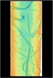
The EM122 multibeam echosounder (MBES) is normally run with standard options enabled and automatic parameter adjustments enabled where possible. This configuration should provide good coverage (swath width), but may not provide optimal coverage under all conditions. These settings will not provide the best data quality. Specifically, reducing swath width is often required to attain the best data quality and density. Consult with the technical staff or other authorities if there are specific requirements for your cruise.
Bathymetry data will be acquired (recorded) using a Kongsberg EM-122. The EM122 sound velocity profile (SVP) will be processed from the Expendable Bathythermograph (XBT) data and uploaded to the EM122 system by the technical staff. The updates will occur at the discretion of the technical staff or at PI request, up to once per day, coincident with XBT deployment.
Should more frequent updates than once per day be required, the science party must supply the necessary probes. They must also supply approx. 30 minutes of personnel time to perform the processing, per profile. Training in processing and uploading the profile to the multibeam will be provided by technical staff.
Sub-bottom Profiler
The Knudsen 3.5 Hz Sub-bottom Profiler (SBP) is normally run synchronized with the EM122 MBES. This sometimes results in a reduction in the Knudsen sampling rate, but minimizes interference with the EM122. PI's who wish to run the Knudsen without synchronizing to the EM122 must discuss this with the Chief Science Officer. If the multibeam is not in use, the Knudsen will be run in internal sync. Knudsen data is recorded in SEG-Y, KEA, and KEB formats.
Magnetics and Gravity
Magnetics
The Langseth carries two Geometrics 882 magnetometers – one being a spare unit. Langseth policy is to deploy the magnetometer only in the work area. The magnetometer is not deployed during transits to and from the work area. The magnetometer must be recovered at less than 3 knots. The magnetometer will not be deployed during OBS recovery or deployment operations.
Gravity
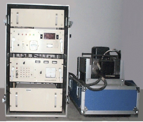
The Langseth is equipped with a Bell Aerospace BGM-3 gravimeter (image below). Gravity data will be handled by the R2R data archive group at LDEO.
XBT
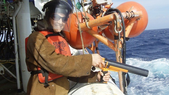
The Langseth carries Sippican T-5 and T-7 Expendable Bathythermograph (XBT) probes, suitable for general oceanography and sound velocity use in the multibeam processing. Langseth deploys one probe daily when possible. Science party assistance (one person, ~20 minutes daily) is required for routine probe launch. Multiple people can be trained on probe launch operations. If no science party members are available to assist with deployments, deployments may be reduced as necessary. Due to space and cost considerations, Langseth does not routinely carry probes in excess of these requirements. PI's who require additional probes or probes of a different type must discuss their needs with OMO before the cruise. PIs who have a specific deployment plan should work with shipboard technical staff during the cruise. The standard cut-off limit for XBT probes will be used unless a specific request is made by the PIs (Probe T-5 to 1850 m and Probe T-7 to 700 m). Other Mk21 probes, e.g. XCTDs and XSVs, may be deployed using the Mk21 system. The LDEO technical staff does not provide these probes.
CTD
The Langseth carries a Sea-Bird Electronics SBE19 Conductivity, Temperature, Depth (CTD) system. This instrument does not have a water sampling system.
Coring
The Langseth does not have a permanent coring setup, however the capability is available from Oregon State University (OSU). In 2012, the Langseth had a successful coring cruise, MGL1208, with the coring team from OSU.
Navigation
The navigation equipment on the vessel is as follows:
- Furuno FE700 echosounder
- Furuno DS50 doppler speedlog
- C-Nav 3050 DGPS
- C-Nav 2000 DGPS
- SImrad GC80 gyrocompass
- Sperry Mark 37 gyrocompass
- POS/MV Integrated Nav System
- Seapath Integrated Nav System
- Spectrum Instruments TM-4 Event Logger
These systems are provided to support seismic operations and the multibeam system. There are no user-configurable options. These systems are operated by the crew and technical staff, and are turned on or secured as necessary. They are normally operated, unless equipment or permit requirements dictate otherwise. All of these instruments output serial data and are logged using the Lamont Data System.
The navigation processing will be performed by the technical staff using the Concept Sprint Navigation Processing System.
Data format: UKOOA P294 (final P190)
Data medium: Electronic
Meteorological
Langseth has an RM-Young Weather Station installed for wind speed/direction, air temp/humidity, and barometric pressure.
Surface Seawater
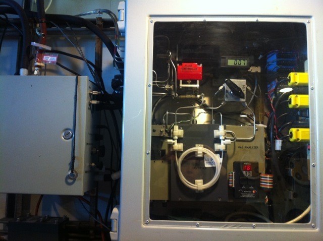
The following meteorological and hydrographical instruments are on the Langseth and are routinely operated:
- LDEO PCO2 (image on right)
- SBE-45 TSG
- Applied Microsystems MicroSV
- Sea-bird Electronics SBE38 Temperature Sensor
Client-provided Instrumentation
Set-up and operation of client-provided instrumentation is the responsibility of the Chief Scientist. The technical staff can assist with serial data feeds and network access. Please inform the OMO office and technical staff before bringing new instrumentation to the vessel.
Technical staff is provided 24-hours-a-day for scientific cruises. The number of sailing staff depends on the cruise objectives and is evaluated on a cruise-by-cruise basis
Technical Staff Responsibilities
It is the responsibility of the technician staff to work in accordance with the issued procedures and within the cruise specifications. They are also responsible for maintaining the equipment, keeping this in optimum condition and using it in accordance with the applicable procedures, work instructions., and manuals. Technicians are responsible for all data gathered, to ensure that it is of maximum achievable quality and properly filed and labeled on the appropriate forms. Technicians communicate with the Chief Science Officer (CSO) on a continuous basis to keep the CSO up-to-date on the status and progress of the work.
The survey technicians are responsible for the maintenance and operation of the survey equipment. This shall include overseeing that correct procedures are used during calibrations and winch operations, and that the data are logged in the correct format with correct electronic. This responsibility extends to assisting with installation and maintenance of the navigation and bathymetry spreads. The survey technicians are also responsible for ensuring that correct procedures are used during the set-up and calibration of the multibeam systems and monitoring of the geophysical data.
The technical support staff shall liaise with the science party to ensure that the best quality data obtainable are recorded. The science party is responsible for all geophysical data processing and interpretation. Data processors are NOT included in the technical support staff. The technical staff will assist, when possible, with other science operations including coring. However, the science party is responsible for in situ testing, storage, and transport of all samples to the onshore curation facility.
The technical support staff can consist of a Chief Science Officer, IT / Navigation Technicians, Data Acquisition Technicians, and Source, Towing & Handling Technicians.
Their responsibilities are as follows:
Chief Science Officer
The Chief Science Officer (CSO) is the senior technician onboard and is the liaison between the cruise participants, the LDEO / OMO staff, the Captain, the LDEO / OMO office and the port agent. The CSO coordinates the support effort among the various parties onboard. The CSO is the first contact for issues related to on-board operations, cruise plans, etc. The CSO is responsible for deployment, recovery, and trim of all towed seismic equipment.
IT / Navigation Technician
The IT / Navigation Technician (IT /NAV) is in charge of navigation system parameters and operations. The navigation technicians are responsible for ensuring that correct procedures are used during the set-up and calibration of the navigation system, logging of all data and sensor information, correct installation, maintenance and operation of the SBES, MBES, and motion sensors.
Data Acquisition Technician
The Data Acquisition Technician (ACQ) assists in deployment, recovery and trim of all geophysical survey equipment, the seismic recording system parameters and operations as well as sound source controller operation.
Source, Towing & Handling Technician or Mechanic
The Sound Source, Towing and Handling Technician (ST&H) is in charge of deploying, retrieving, and maintaining the sound source as well as other seismic towed equipment.
Safety is of the utmost importance! The science party will comply with all the vessel safety rules and regulations. In accordance, most personal protective equipment (PPE) will be provided onboard. However, the science party is asked to pack safety toe shoes (composite toes if not steel toes) to work on the back deck. Coveralls or sturdy clothing is recommended for back deck work. Closed toed shoes are necessary in the galley. The Chief Scientist may have more safety requirements based on the science objectives (e.g., safety glasses in the rock cutting lab). Life jackets and survival suits are provided on the vessel.
The Captain has the final authority for all safety-related matters posing any danger to the ship and/or anyone aboard it. Additionally, if anyone onboard finds that unsafe conditions exist, they have the authority to stop any related shipboard science until the situation is corrected. This would include issues of industrial, marine, or laboratory safety.
Orientation will be conducted for the on-coming science party. This will include a safety briefing and vessel walk-through.
Safety meetings and drills are mandatory USCG requirements.
The R/V Marcus G. Langseth is a US flagged vessel, and can therefore be subject to MARSEC (marine security). All engineering spaces and vessel safe operation spaces are off limits to non-affiliated and/or non-escorted personnel. All persons intending to board the vessel must provide positive proof of identification. A Passport, US driver's license, or TWIC (transportation workers identification credential) are accepted. Non-crew cannot enter a US port facility or board the Langseth unescorted without a TWIC. A gangway watch is maintained and all non-crew are required to sign in and sign out.
Science Party Briefing and Safety Orientation (PDF)
Weather will be continually monitored while at sea. Weather forecasts are available from the following systems:
The Financial Management and Financial Reporting Guide for the R/V Langseth gives information about the purpose of the vessel itself, current position descriptions aboard the ship, and places the highest emphasis upon the financial procedures for operating the ship. Complete financial Standard Operating Procedures (SOPs) are included.

